Assembly & Building Guide
Planter Garden
✓ Field-Verified Build
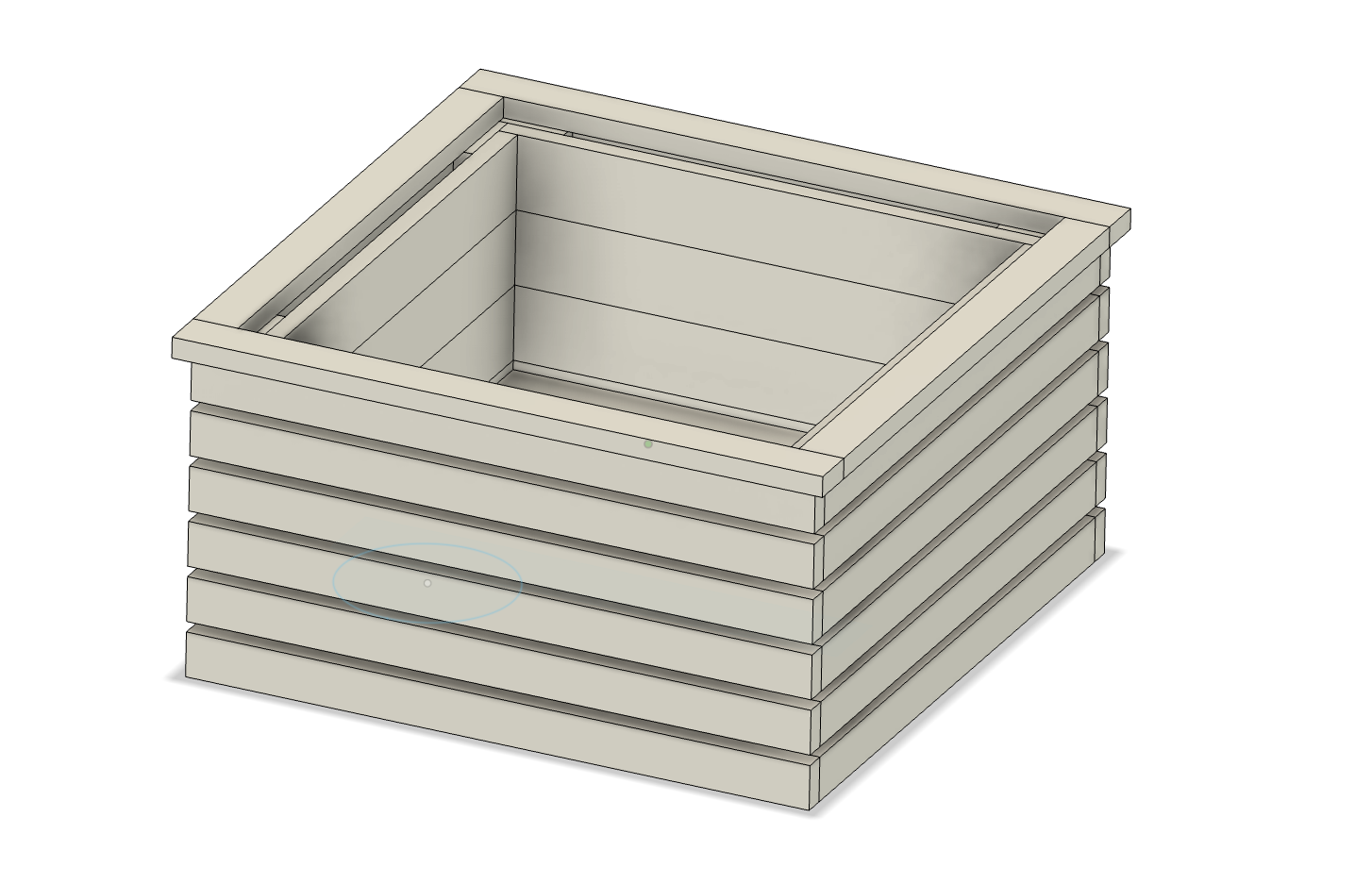
626 mm
Width & Depth
338 mm
Total Height
60 pieces
Parts to cut
Assembly & Building Guide
Workshop Reference
The three stops are listed in construction order. Stop A (300 mm) cuts the corner posts for Step 1. Stop B (596 mm) covers all wall slats and cladding using offcuts as spacers — set it once and work through each length by adding spacers without moving the stop. Stop C (626 mm) cuts the top lip last.
Stop A — 300 mm · 8 pieces
Set stop to 300 mm
| Cut length | Spacer stack | Total spacer | Qty | What |
|---|---|---|---|---|
| 300 mm | — | — | 8 | Corner post arms → 4 L-shaped posts |
| Stop A subtotal | 8 pieces | Set directly — 300 mm reference measurement | ||
Stop B — 596 mm · 48 pieces · never move the stop
Reset stop to 596 mm
| Cut length | Spacer stack | Total spacer | Qty | What |
|---|---|---|---|---|
| 596 mm | — | — | 12 | Outer cladding — long sides |
| 560 mm | 2 × 18 mm | 36 mm | 12 | Outer cladding — short sides |
| 516 mm | 2 × 18 mm + 2 × 22 mm | 80 mm | 8 | Long side-wall slats |
| 472 mm | 2 × 18 mm + 4 × 22 mm | 124 mm | 16 | 8 × short side-wall slats + 6 × floor slats + 2 × floor bearers (43 × 18 mm) |
| Stop B subtotal | 48 pieces | Add spacers progressively — never reset the stop | ||
Stop C — 626 mm · 4 pieces · top lip only
Reset stop to 626 mm
| Cut length | Spacer stack | Total spacer | Qty | What |
|---|---|---|---|---|
| 626 mm | — | — | 2 | Top lip — long sides |
| 540 mm | 2 × 43 mm (board width) | 86 mm | 2 | Top lip — short sides |
| Stop C subtotal | 4 pieces | Use the 43 mm board width itself as the spacer | ||
| Grand Total | 60 pieces — 3 stop settings | Stop A (8) · Stop B (48) · Stop C (4) |
Materials
Corner Posts — assembled in pairs to form 4 L-shaped posts
74 mm wide × 22 mm thick
| Length | Qty | Role | Saw Setup | |
|---|---|---|---|---|
| 300 mm | 8 | Corner post arms — 2 per post, glued & nailed at 90° to form L-shape | Stop A — direct | |
| Subtotal | 8 pieces → 4 posts | Cut from 74 × 22 mm board | ||
Profile A — Inner Structure
74 mm wide × 22 mm thick
| Length | Qty | Role | Saw Setup | |
|---|---|---|---|---|
| 472 mm | 8 | Short side-wall slats (4 per side, 2 sides) | Stop B · 2×18 + 4×22 mm | |
| 472 mm | 6 | Floor slats | Stop B · 2×18 + 4×22 mm | |
| 516 mm | 8 | Long side-wall slats | Stop B · 2×18 + 2×22 mm | |
| Subtotal | 22 pieces | From one continuous 74 × 22 mm board | ||
Profile B — Outer Cladding & Top Lip
43 mm wide × 18 mm thick
| Length | Qty | Role | Saw Setup | |
|---|---|---|---|---|
| 472 mm | 2 | Floor bearers — run along the short side walls, floor slats rest on top | Stop B · 2×18 + 4×22 mm | |
| 540 mm | 2 | Top lip — short sides | Stop C · 2×43 mm | |
| 560 mm | 12 | Outer wall cladding — two sides (6 rows each) | Stop B · 2×18 mm | |
| 596 mm | 12 | Outer wall cladding — two sides (6 rows each) | Stop B — direct | |
| 626 mm | 2 | Top lip — long sides | Stop C — direct | |
| Subtotal | 30 pieces | From one continuous 43 × 18 mm board | ||
| Batten | Cuts from this batten | Waste |
|---|---|---|
| 1 – 4 | 3 × 596 mm each (12 pieces total) | 42 mm each |
| 5 – 8 | 3 × 560 mm each (12 pieces total) | 150 mm each |
| 9 | 626 mm + 626 mm + 540 mm | 38 mm |
| 10 | 540 mm + 472 mm + 472 mm | 346 mm |
| Grand Total | 60 pieces | All from 74 × 22 mm and 43 × 18 mm timber | |
Fixings & Gluing
Step 1 — Choose your nail gauge
18 gauge or 16 gauge — both work for this build
| Gauge | Wire diameter | Holding power | Splitting risk | Best suited to |
|---|---|---|---|---|
| 18 gauge | 1.2 mm | Lower — glue carries the load | Very low | Cedar cladding & top lip (43 × 18 mm). Safe near edges on narrow, thin boards. |
| 16 gauge | 1.6 mm | Higher — good mechanical grip | Moderate — keep 15 mm+ from board ends | Inner frame & corner posts (74 × 22 mm). More confidence on structural joints. |
Step 2 — Nail lengths (same for both gauges)
Two lengths — 32 mm and 50 mm, stainless steel
| Nail length | Use | Reasoning |
|---|---|---|
| 32 mm | Corner post L-joint · outer cladding into post arm · top lip · floor slats into bearers | Total timber at these joints is 36–40 mm — a 32 mm nail leaves ~10–12 mm penetration into the receiving piece, with glue carrying the structural load |
| 50 mm | Wall slats (22 mm) into the deep face of the corner posts | The corner post face is 74 mm wide, giving 28 mm of solid penetration — enough to hold the slats firmly even if the glue line is thin |
Gluing — waterproof wood glue throughout
Application & technique
| Joint | Advice |
|---|---|
| Corner post L-joint | Apply glue to the long edge of one arm before pressing the second arm flat against it at 90°. Clamp while the glue cures — do not rely on the nails alone to hold the joint square. Skew the nails slightly so they cross in the glue line for better mechanical grip. |
| Wall slats into corner posts | Apply glue to the inner face of the corner post arm before nailing each slat in. Work one side at a time so the glue does not start to set before the slats are in position. |
| Outer cladding slats | Apply glue to the back face of each cladding slat before nailing. Keep nail heads in a neat line for a clean finish. |
| Top lip butt joints | Apply glue to the end-grain butt joints at each corner. Wipe away any squeeze-out immediately with a damp cloth before it skins over. |
Construction
Step 01 of 10
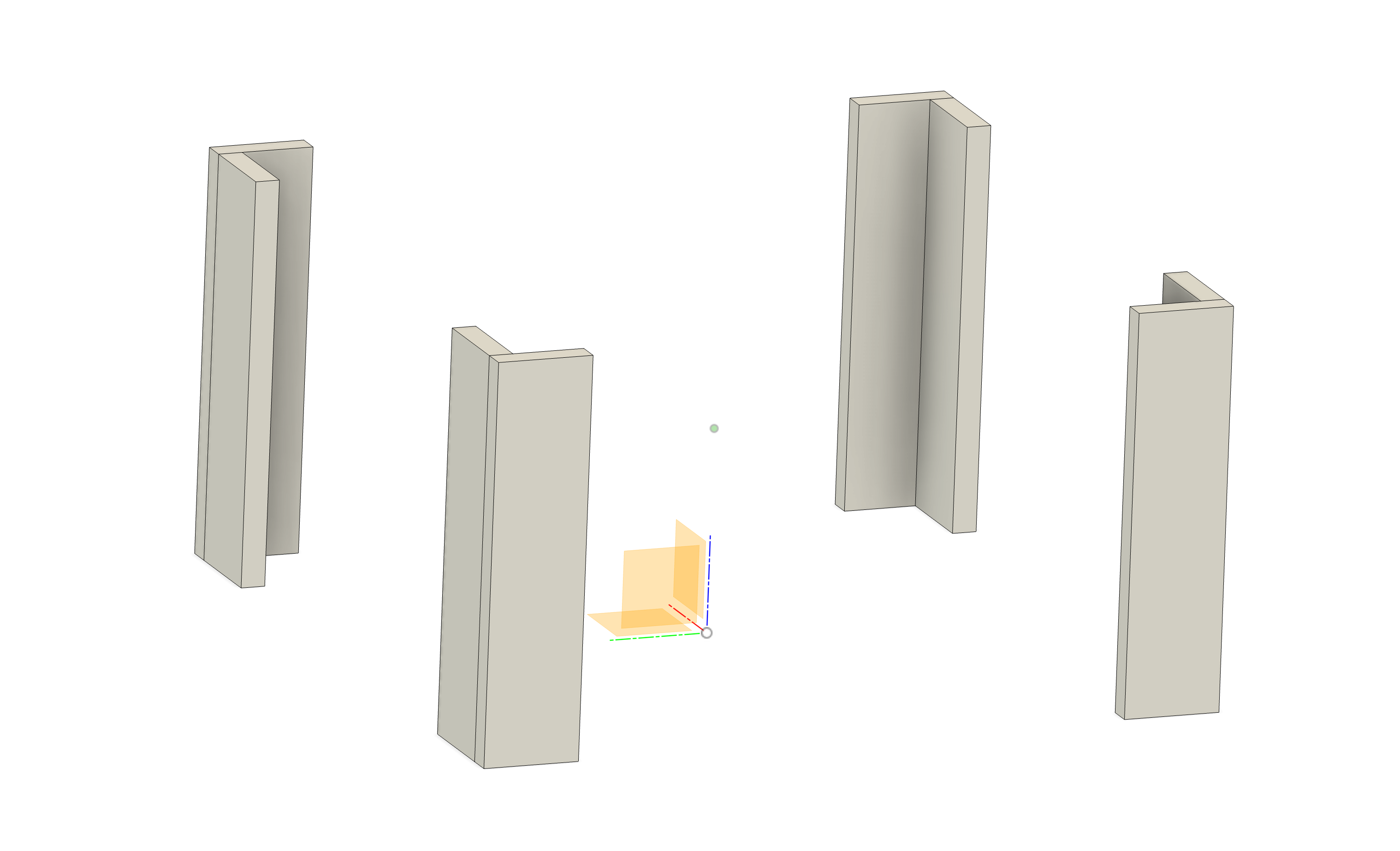
Each L-shaped corner post is made from two 300 mm boards joined at 90°. Apply waterproof wood glue to the long edge of one board, press the second board flush against it to form an L in cross-section, and nail through with stainless steel nails to clamp while the glue sets.
Make all four posts first and let them cure fully before beginning wall assembly.
Parts used in this step
8× 300 × 74 × 22 mm → 4 L-shaped posts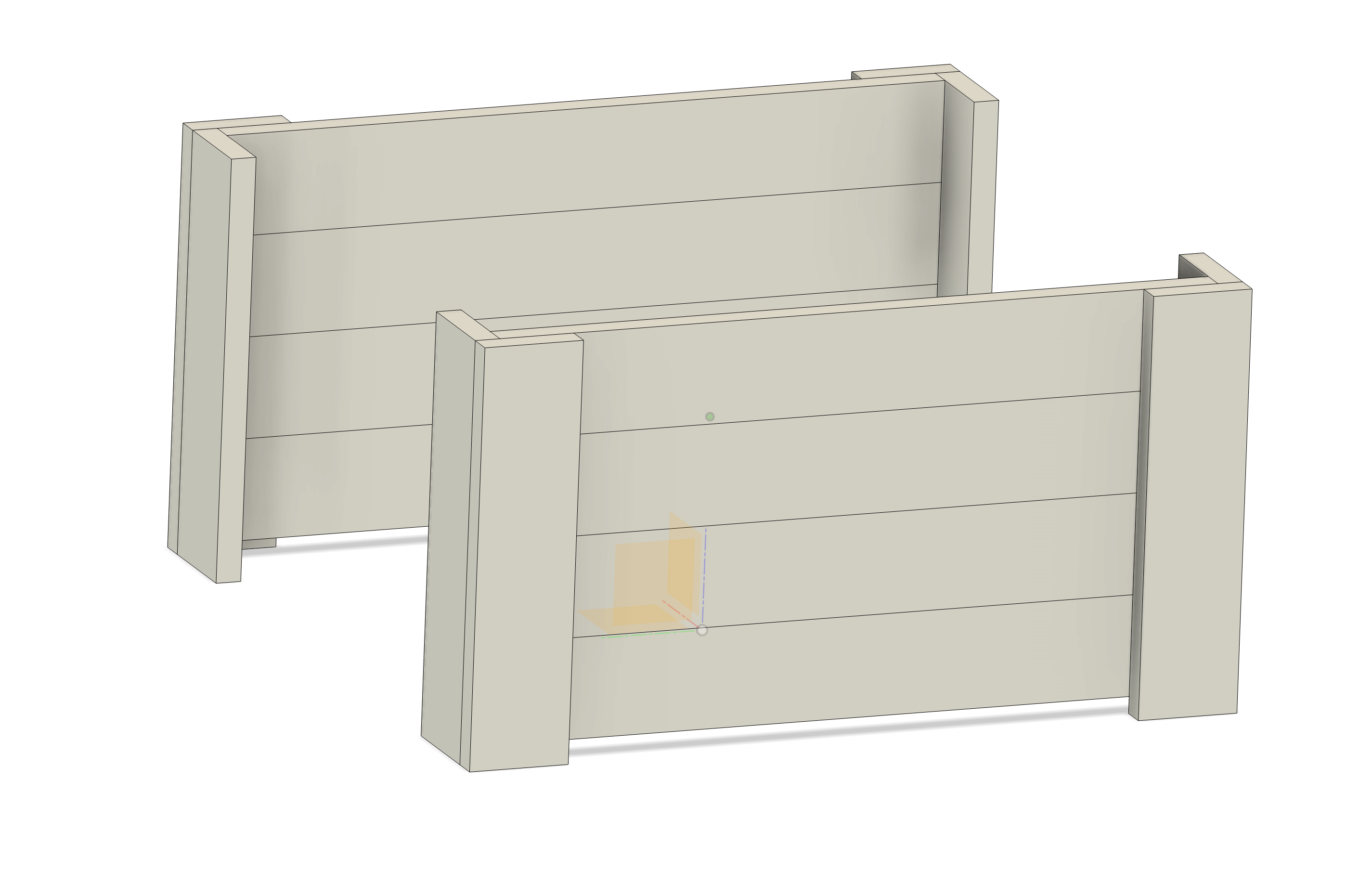
Step 02 of 10
Apply waterproof wood glue to the inner face of each corner post arm, then nail the 516 mm slats horizontally into the posts. Start from the top — align the first slat flush with the top of the corner posts, then work downward, butting each board tight against the one above with no gap between them.
With 4 slats stacked tightly (4 × 74 mm = 296 mm), the bottom of the last slat will sit above the bottom end of the corner posts — this is intentional. The posts extend below the wall slats by design to support the floor structure.
Keep both panels flat on a workbench to ensure they are square before the glue sets.
Parts used in this step
8× 516 × 74 × 22 mm (Body 29–36) 4× L-shaped corner posts (2 per panel)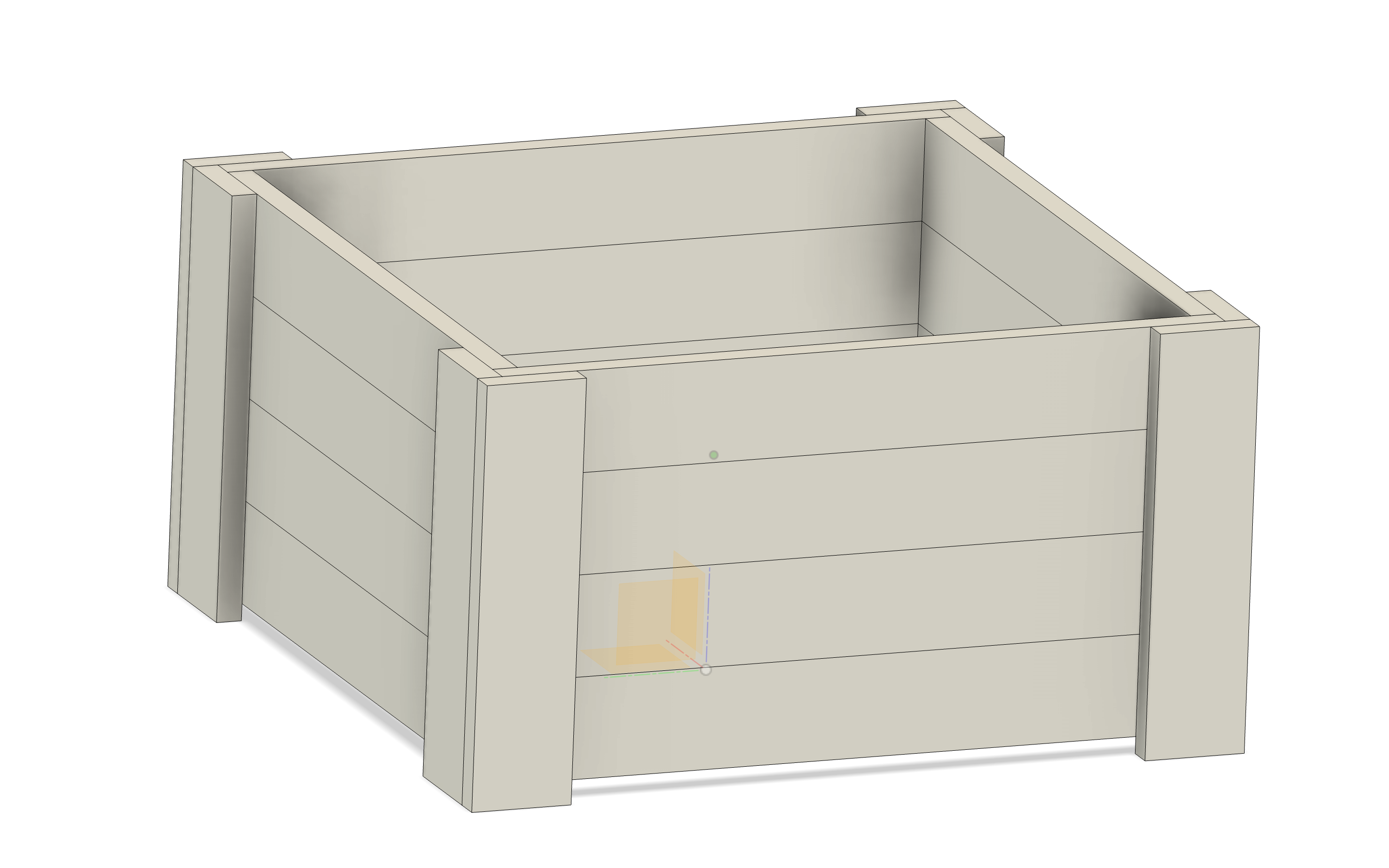
Step 03 of 10
Stand the two long side panels upright and connect them by nailing the 8 short side-wall slats into the open arms of the corner posts — 4 slats per short side, starting from the top and butting tight against each other, exactly as in Step 02.
Apply waterproof wood glue to the inner face of each corner post arm before nailing. Check for square by measuring the diagonals — they should be equal. The inner box is now fully framed on all four sides.
Parts used in this step
8× 472 × 74 × 22 mm — short side-wall slats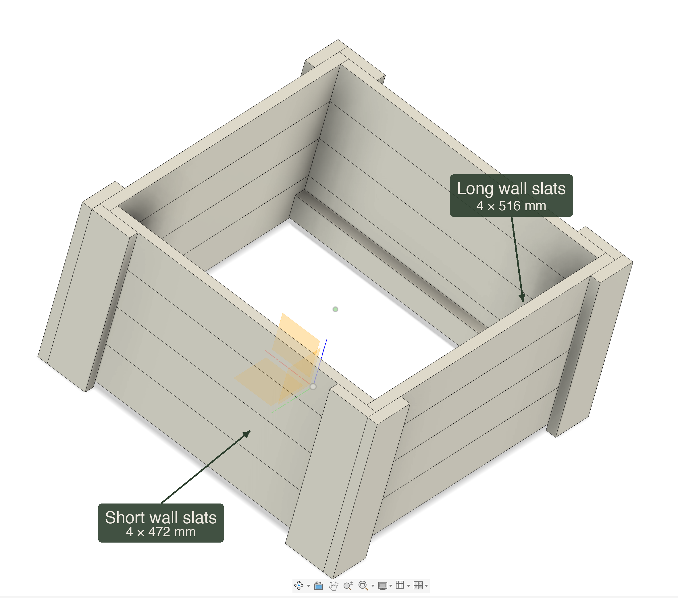
Step 04 of 10
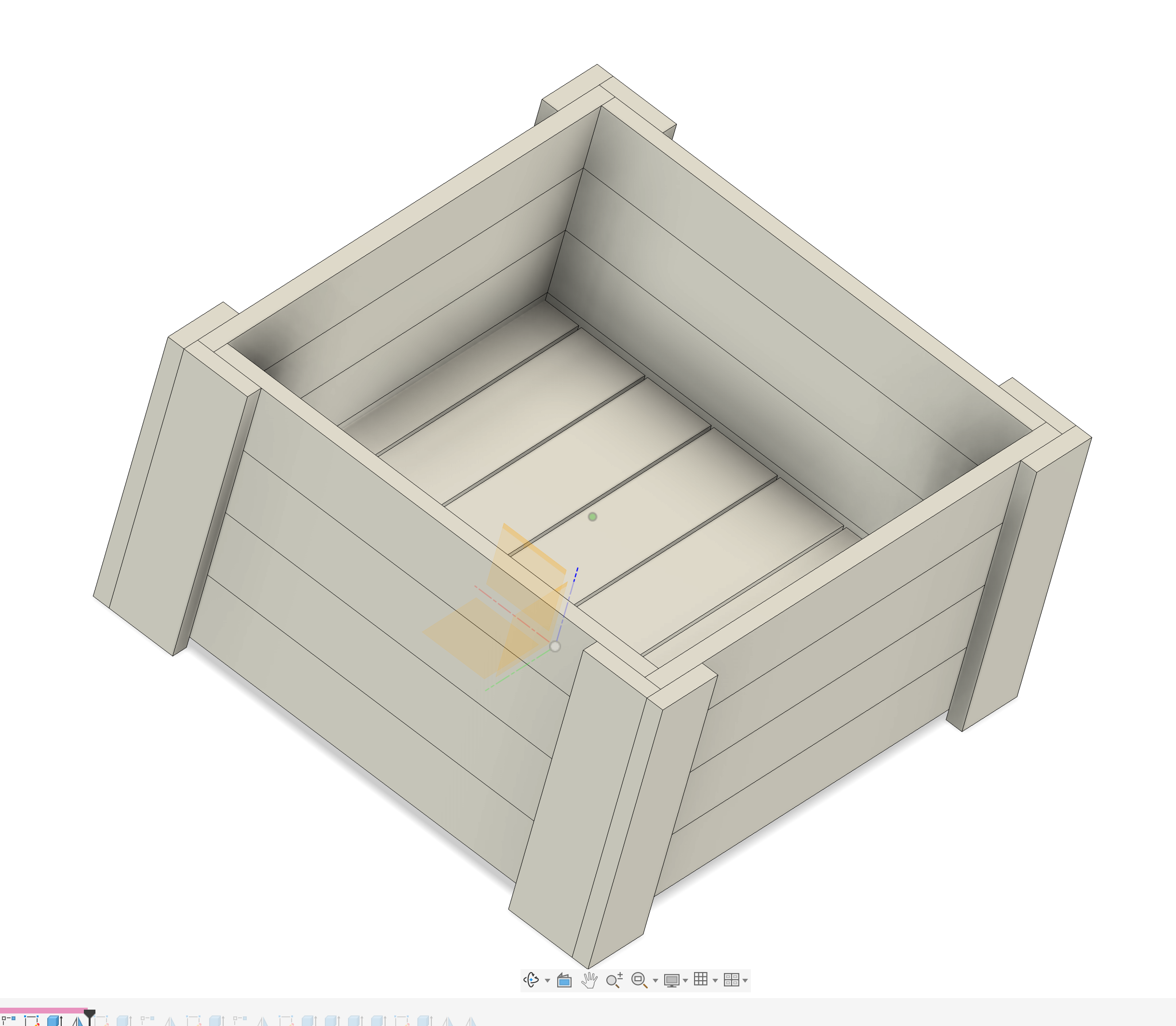
The inner box is now fully framed with all four walls in place. This is the best moment to check that all corner posts are plumb and all wall slats are flush on the interior face.
The box is still open at the bottom. The corner posts are flush with the top of the wall slats — the extended section is at the bottom, where the posts reach below the wall frame to carry the floor bearers and, later, the caster wheels.
No new parts — alignment check
Step 05 of 10
Before anything, decide the floor height. The floor position is variable — it determines how much of the corner posts extend below it, which sets how far the bottom of the outer cladding sits above the ground. Choose the depth based on your wheel size and desired clearance. Mark a level line on the inside face of both short side walls at the chosen height.
Install the two floor bearers first. Nail and glue one 472 × 43 × 18 mm bearer along each short side wall at the marked line, flat face up. These two planks run the full width between the long side walls and carry all the floor slats.
Starting from one side, lay the 6 floor slats across the bearers, spanning between them. Space each slat approximately 5 mm apart for drainage. Work consistently from the starting side — do not adjust spacing mid-run or the last gap will be uneven.
The last slat will need to be ripped to width. Measure the gap left after placing the 5th slat, subtract 5 mm for the final drainage gap, and rip the 6th slat to that width on the table saw.
Nail the floor slats down into the bearers using stainless steel nails.
Parts used in this step
2× 472 × 43 × 18 mm — floor bearers (Profile B) 6× 472 × 74 × 22 mm — floor slats (Profile A)Step 05 detail — Adjusting floor height & trimming the last slat
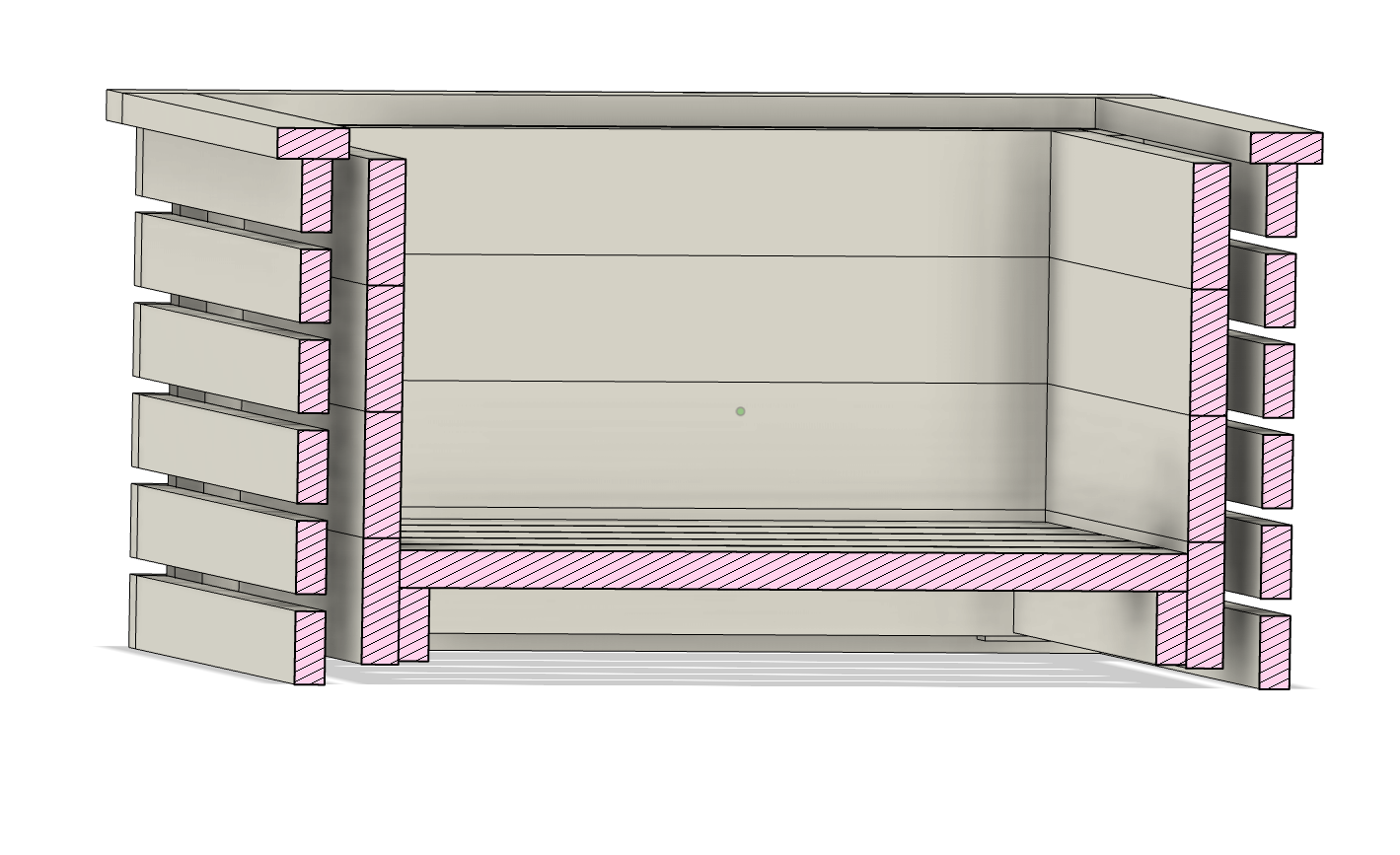
Floor set lower The outer cladding sits close to the ground. Suits smaller caster wheels or a static planter without wheels. Less of the corner posts extend below the floor.
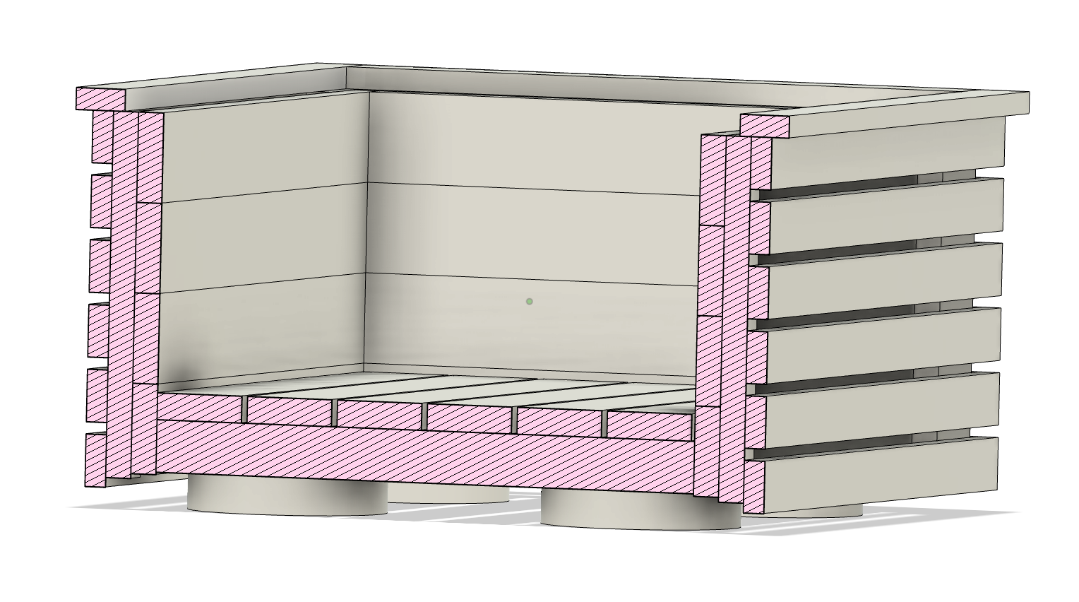
Floor set higher The corner posts extend further below the floor, lifting the outer cladding clear of the ground. Required for larger caster wheels and gives more clearance for drainage or uneven surfaces.
Step 06 of 10
Start from the top. Apply waterproof glue to the contact face of the first slat and nail it flush with the top of the corner posts. This first row sets the reference — work downward from here, spacing each subsequent slat approximately 10 mm below the one above using a spacer block for consistency.
Clad the two short faces first (560 mm slats), then the two long faces (596 mm slats). The longer slats overhang the corners to cover the end grain of the shorter ones — this sequence is what makes the corners look clean. Nail at each end into the corner posts and keep nail heads in a neat line.
Parts used in this step (ongoing)
12× 560 × 43 × 18 mm (Profile B) 12× 596 × 43 × 18 mm (Profile B) Note: 486 × 43 × 18 mm floor bearers already installed in Step 05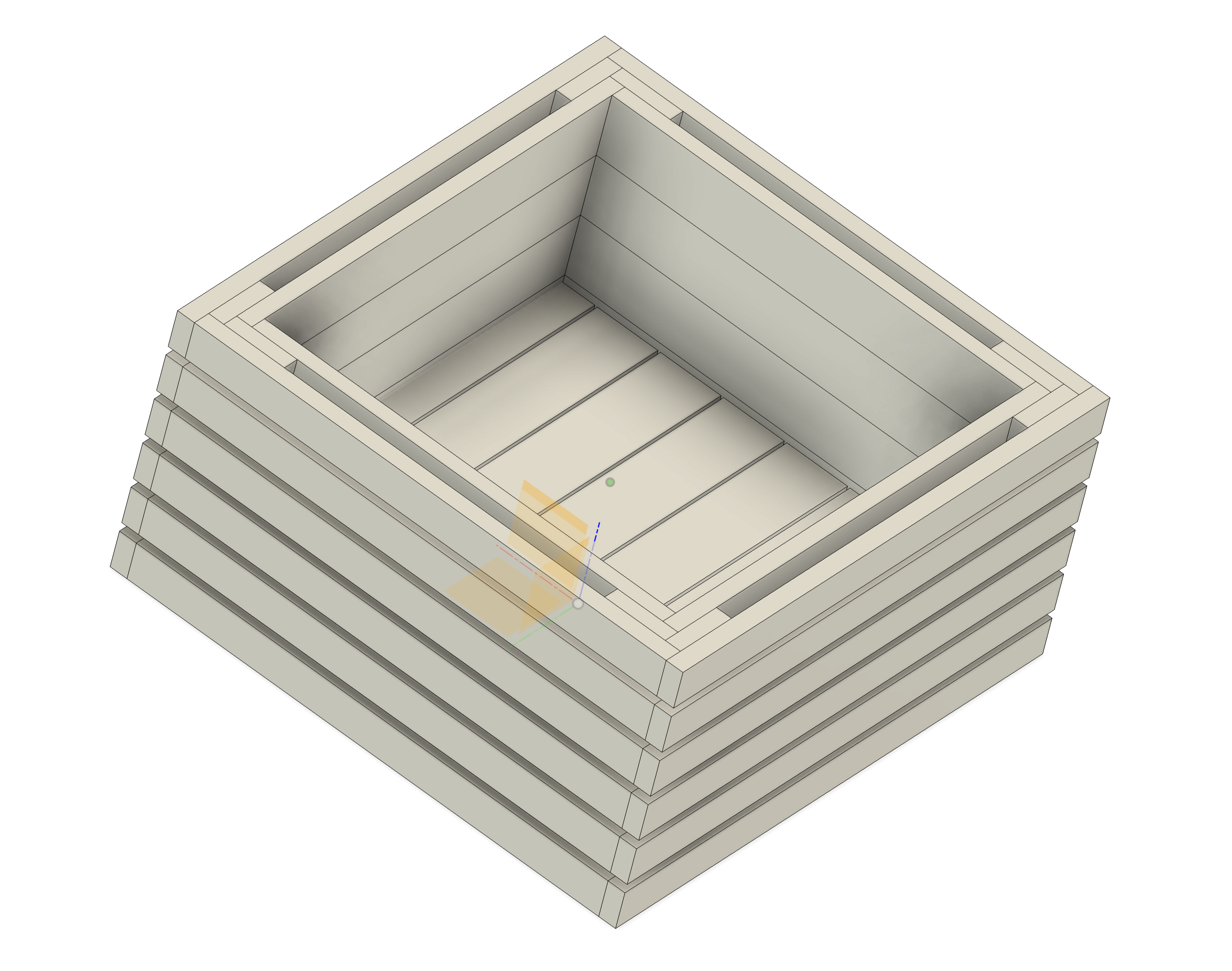
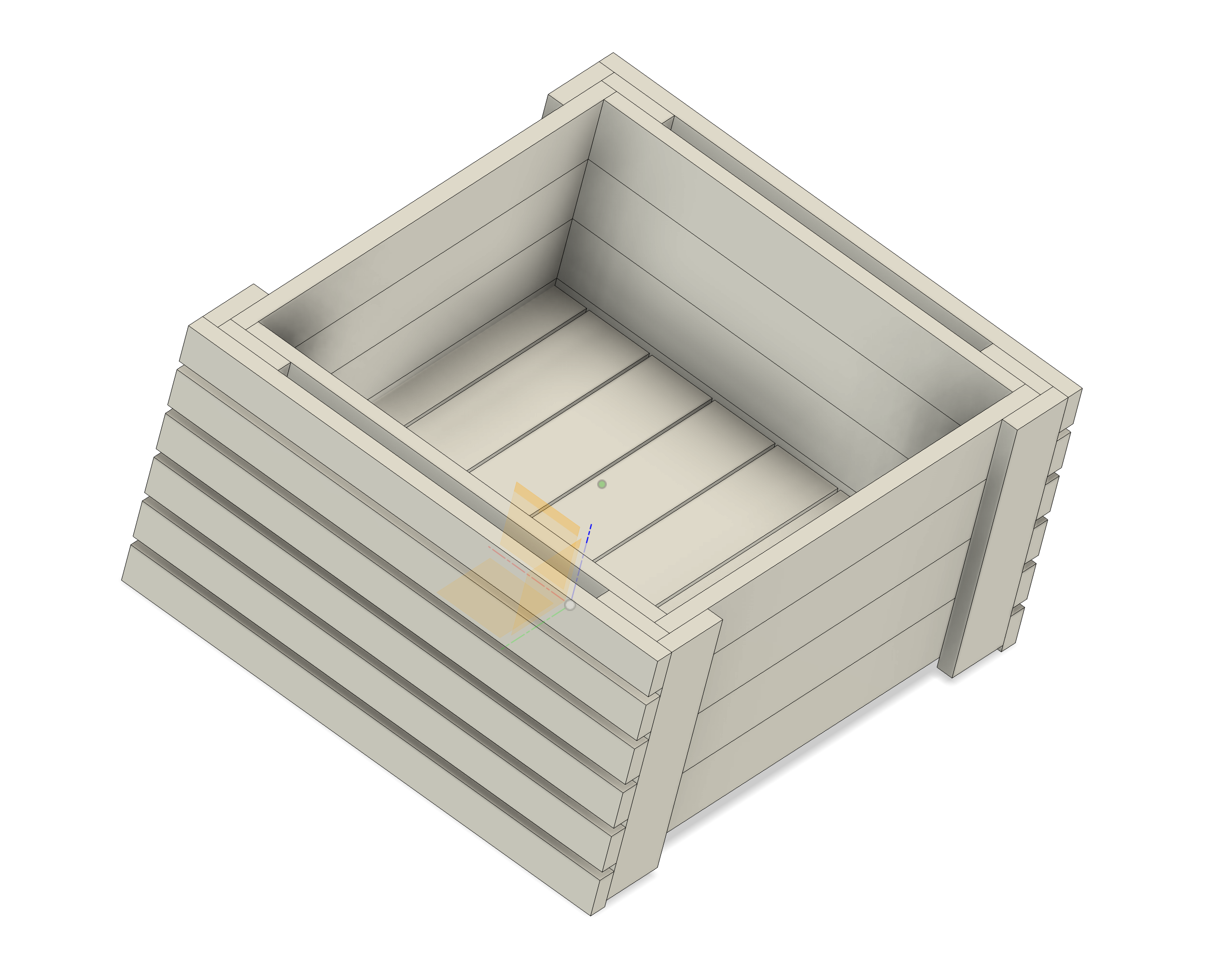
Step 07 of 10
Continue downward, gluing and nailing 6 rows of slats per side with a 10 mm gap between each row. The corner posts absorb all the fixings and are hidden once cladding is complete.
The last row will overhang below the bottom of the inner structure — this is by design. The overhang conceals the gap between the inner frame and the ground, giving the planter a clean, finished appearance from the outside.
Continuing from Step 06
6 rows × 4 sides = 24 cladding slats total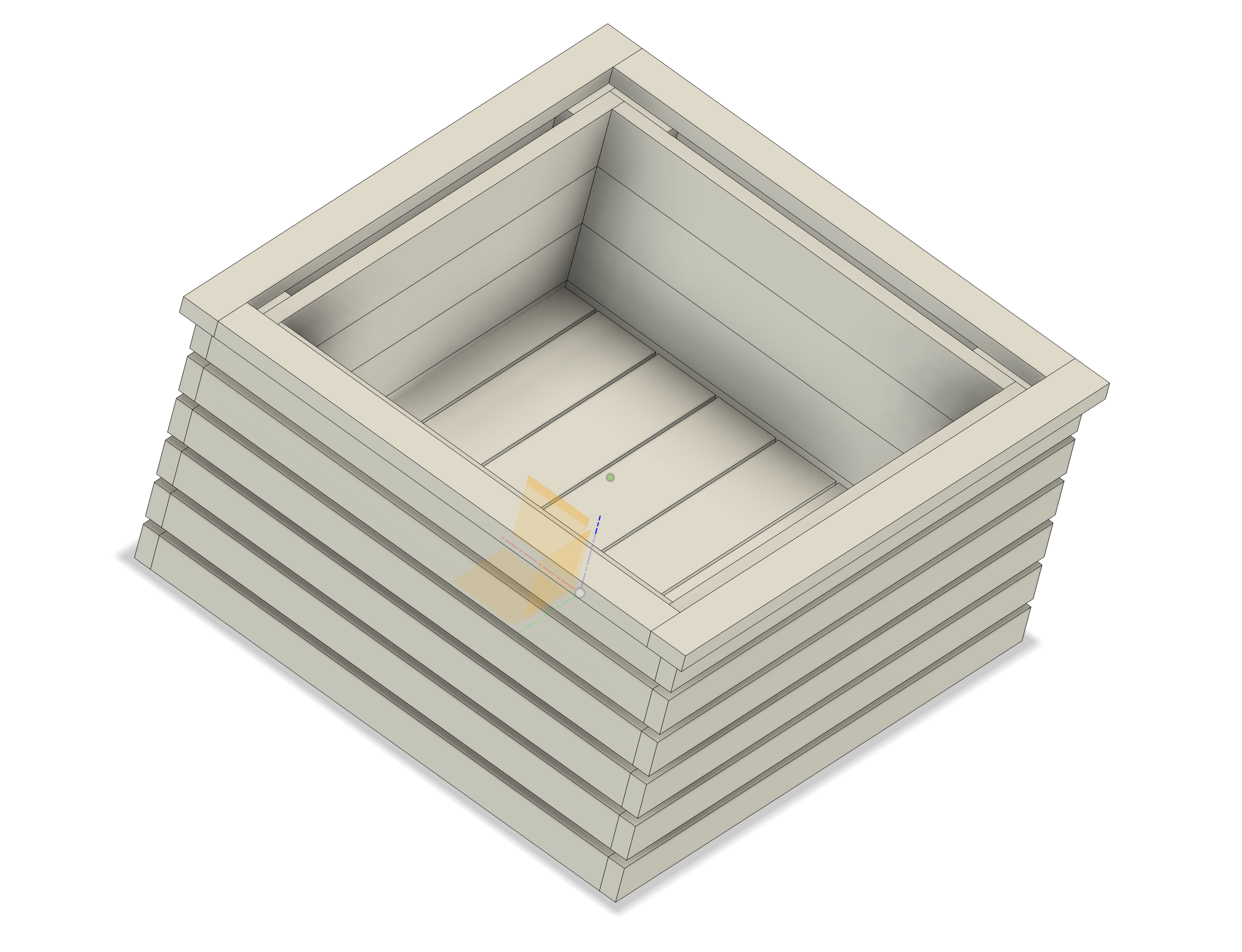
Step 08 of 10
Lay the four top lip boards flat across the top of the box, forming a wide rim. The two 626 mm boards run the full length of the long sides; the two 540 mm boards fit between them on the short sides.
The cap boards extend slightly inward over the inner box wall, creating a neat ledge. Apply waterproof glue to the butt joints at the corners, then nail down through the cap into the top of the corner posts. Wipe away any glue squeeze-out before it sets.
Parts used in this step
2× 626 × 43 × 18 mm (Profile B) 2× 540 × 43 × 18 mm (Profile B)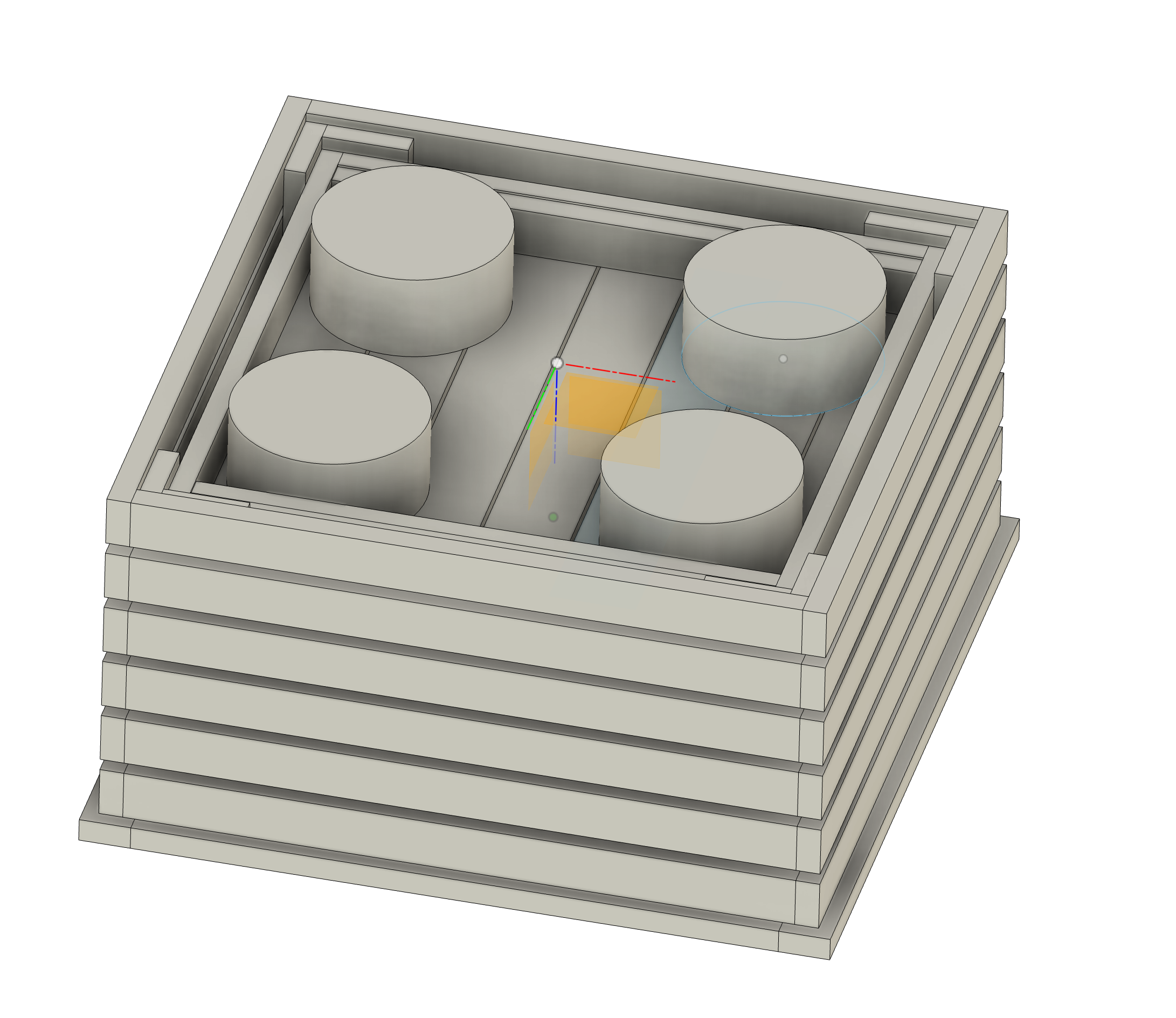
Step 09 of 10
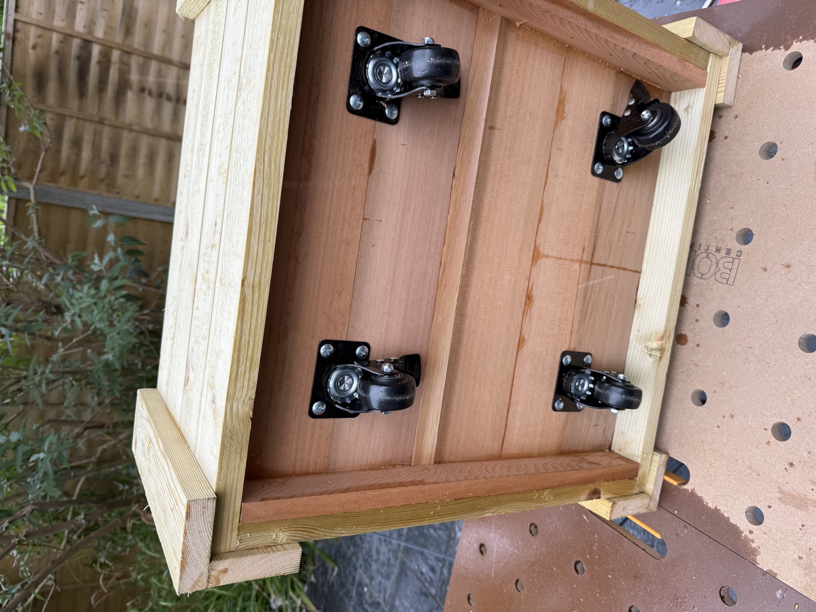
Flip the planter upside down to give clear access to the underside of the floor. Position one caster in each quadrant, keeping each mounting plate at least 40 mm from the nearest floor slat edge to leave room for the screws and to avoid splitting the timber near the joint.
The GBL 50 mm casters mount via a top plate — mark the screw hole positions with a pencil, pre-drill pilot holes to prevent splitting, then fix using the screws supplied with the pack. The swivel head rotates through approximately 80–90 mm — ensure no floor slat joints or existing fixings fall within that radius of each mounting centre.
Once all four casters are fitted, flip the planter upright and check that it sits level. If one wheel is slightly higher, check the mounting plate is fully flat against the floor slat — a small packing shim can correct any tilt.
Not in cutting list — purchase separately
4× GBL swivel caster wheel — 50 mm, with brake & screws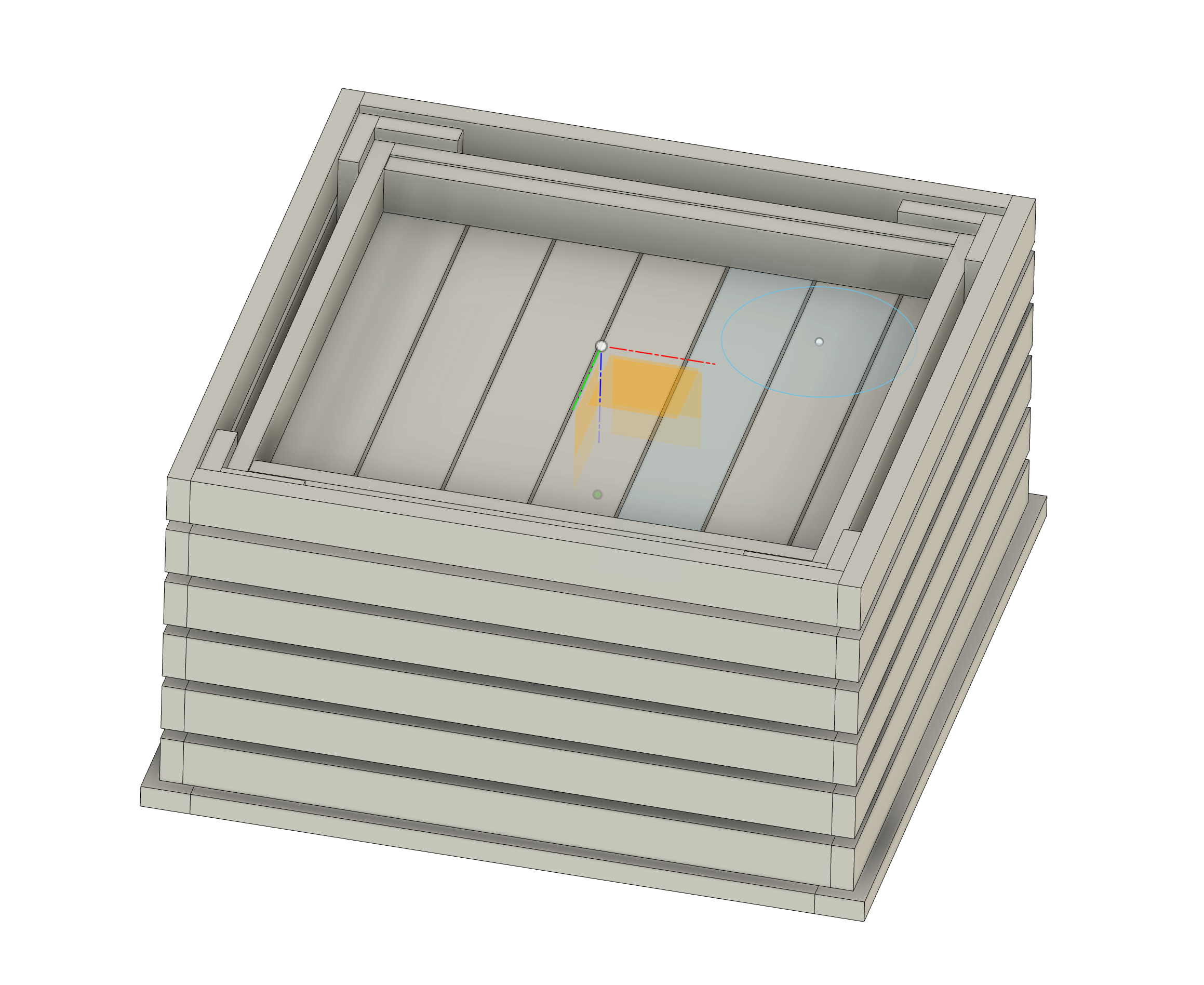
Step 10 of 10
The planter is complete. The outer cladding fully conceals the inner structure; the wide top lip provides a clean finish and prevents rain from pooling on end grain. The four swivelling wheels allow the planter to be rolled across the garden for cleaning or repositioning.
Apply exterior wood finish or oil to all exposed surfaces before placing the planter outdoors. Sand any sharp corners on the top lip.
Fit a planter liner before filling with soil. Direct soil contact will draw moisture into the inner structure year-round regardless of external oiling. A heavy-duty plastic sheet or a purpose-made fabric liner stapled to the inner walls will significantly extend the life of the timber.
Finishing
Exterior wood oil or paint Sandpaper 120 → 180 grit Stainless steel nails Waterproof wood glueField-Verified Build
One planter built. These photographs document the real construction sequence, from workshop setup in the garden to the finished box. All dimensions, spacings and techniques shown here match the cutting list and assembly steps exactly.
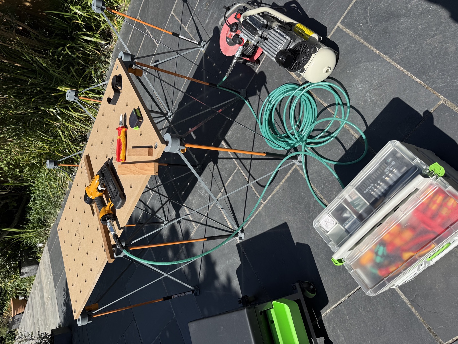
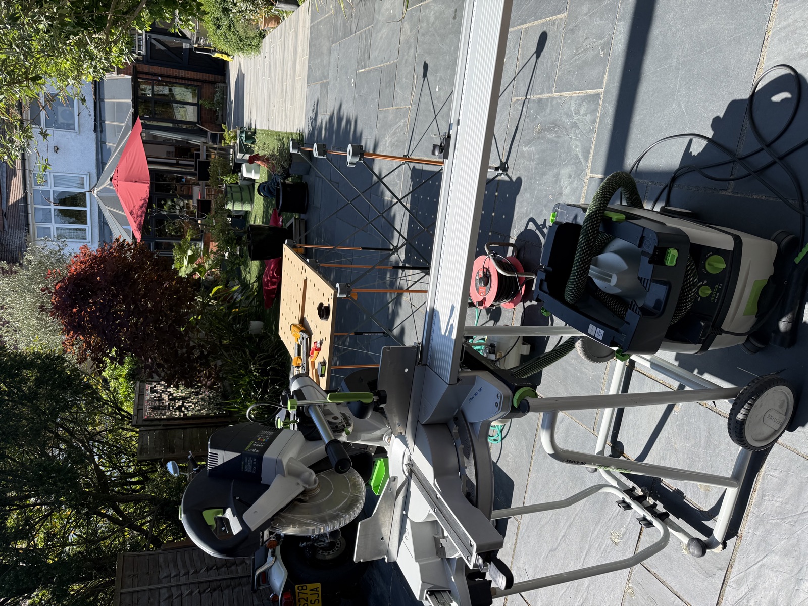
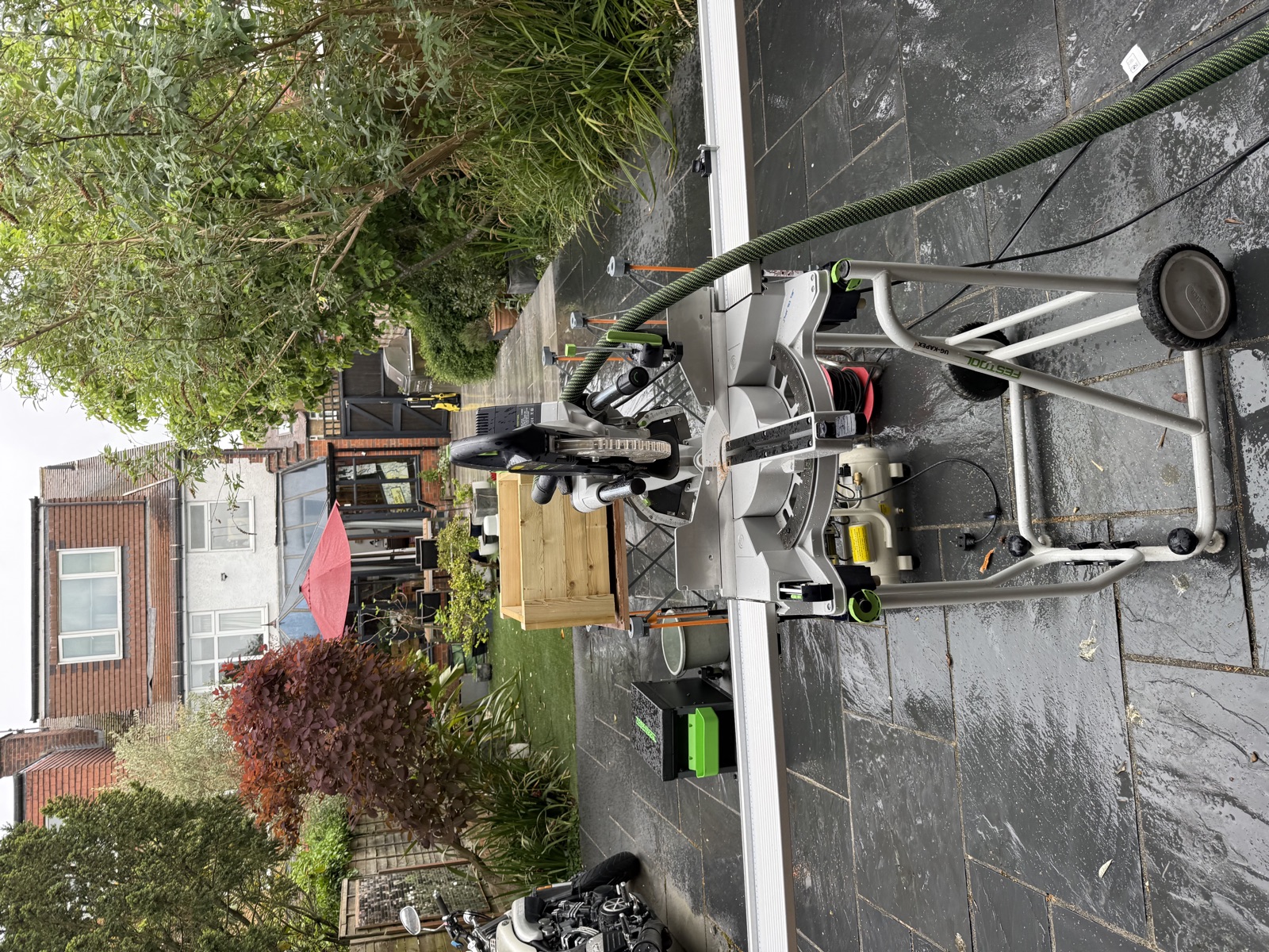
Stage 1 of 5 · Workspace & Saw Setup
The mitre saw is set up outdoors on the patio with a dust extractor. Cedar battens and treated pine boards are staged for cutting. The spacer method starts here — Stop A set to 300 mm for the corner post arms.
 Festool mitre saw + dust extractor — garden workshop setup
 Boards staged, saw ready — spacer method begins
 Cedar battens (43×18) and pine (74×22) ready for Stop A
Stage 2 of 5 · Corner Posts & Frame
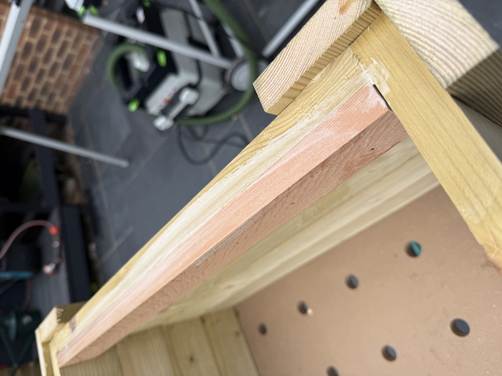
L-shaped corner posts are glued and nailed, then the long side panels are assembled flat on the workbench. The Bora Centipede outfeed table keeps the frame stable while the glue cures. First cedar slat visible in top corner — confirming the two-profile system works.
 Corner posts assembled — first cedar slat test-fitted at top
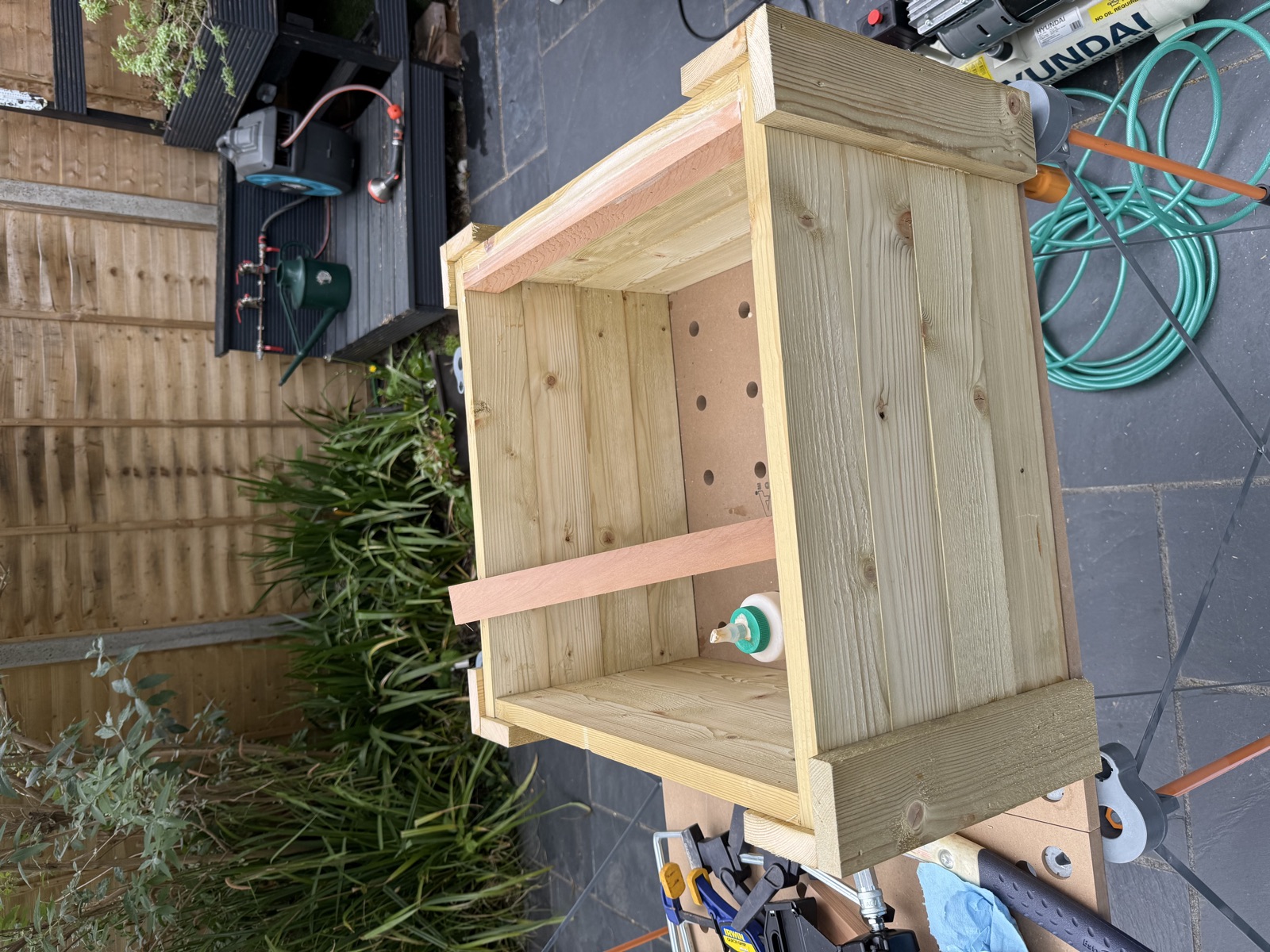
 Full inner box — four walls joined, open at bottom for floor
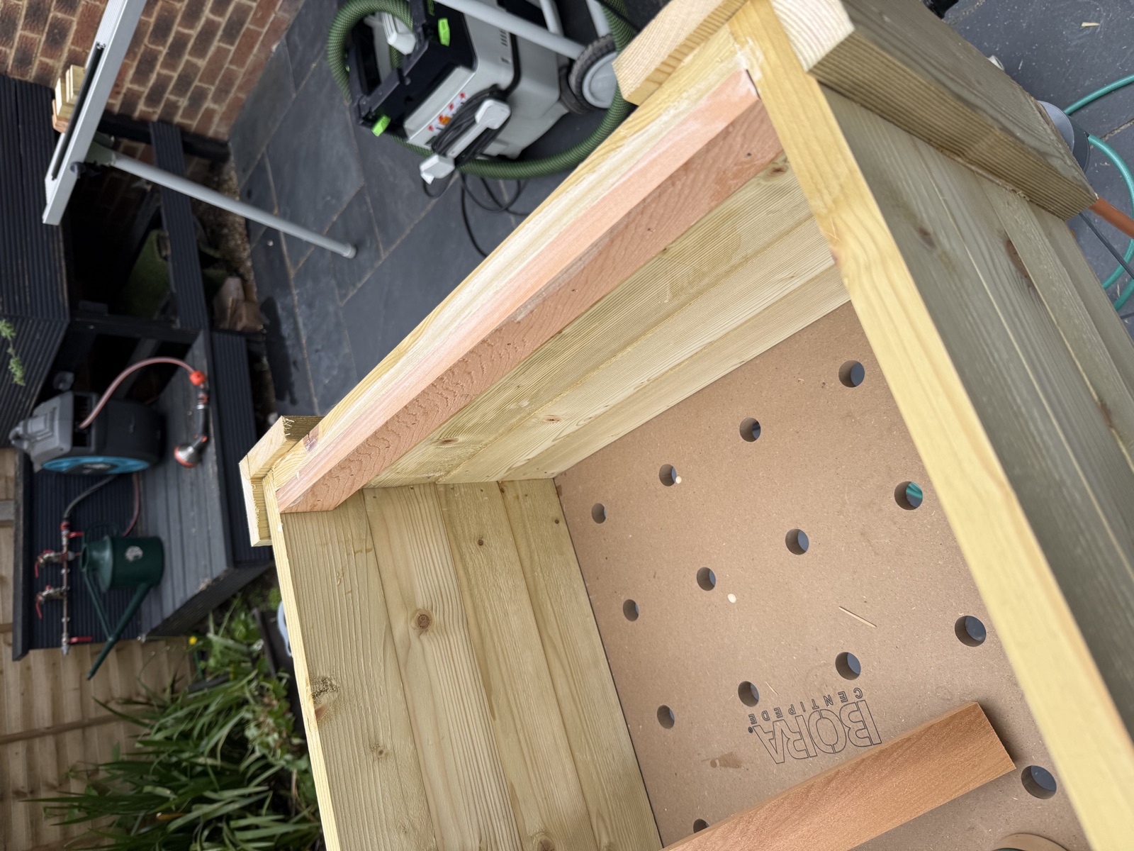
Stage 3 of 5 · Floor & Inner Structure
Floor bearers nail in along the short walls at the marked height line. Six pine slats span the bearers with 5 mm gaps for drainage — the last slat ripped to width on the table saw. The inner structure is complete and rigid before any cladding begins.
 Floor bearers nailed in — 5 mm spacing marks on short walls
 Floor slats across bearers — 5 mm gaps for drainage
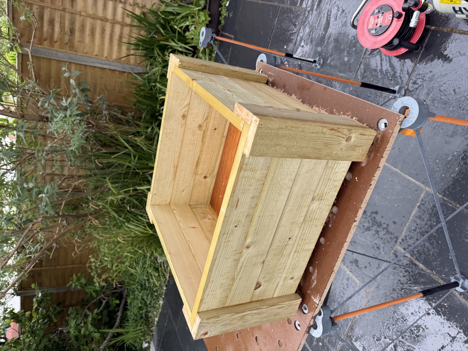 Inner box complete — all walls and floor in, ready for cedar
Stage 4 of 5 · Cedar Cladding & Top Lip
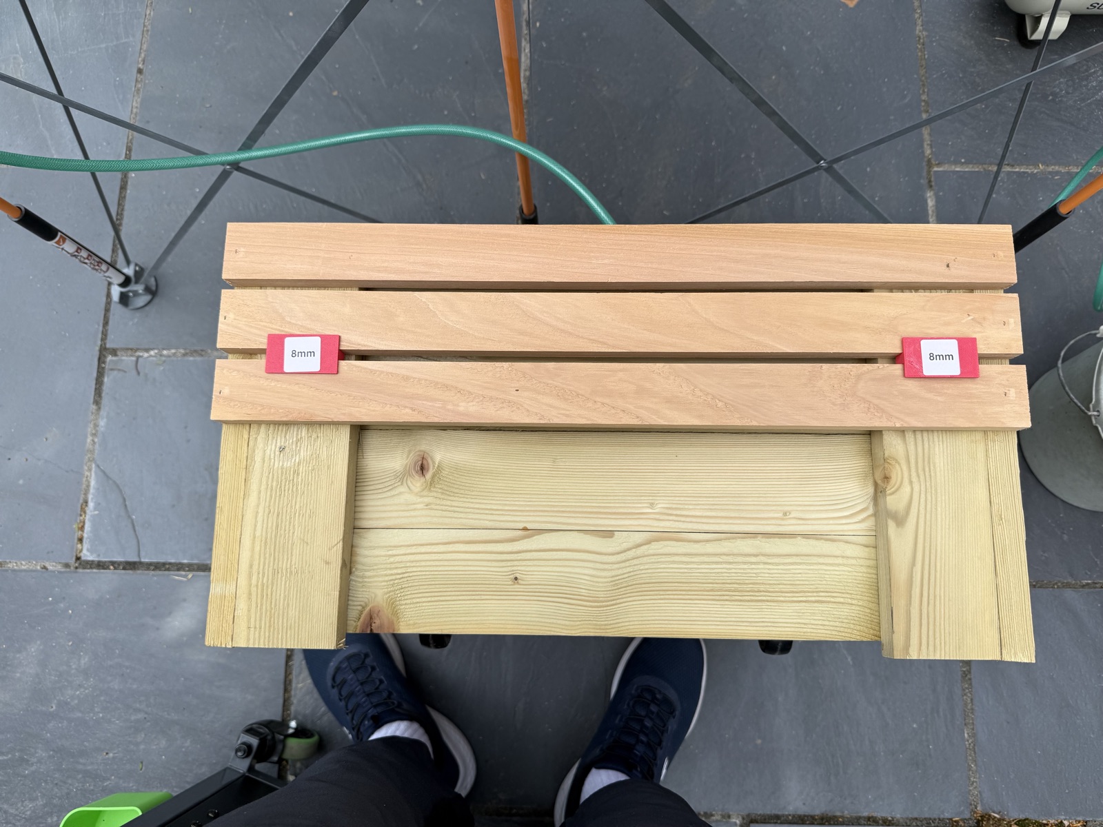
Short sides clad first (560 mm slats), then long sides (596 mm), each row started flush with the top of the corner posts and spaced 10 mm apart using a scrap offcut as a spacer. The final row overhangs below the inner frame to conceal the structure. Top lip fitted last — long boards first, then short.
 Cladding started — short side first, 10 mm spacer between each row
 Two sides complete — gap reveals inner pine frame
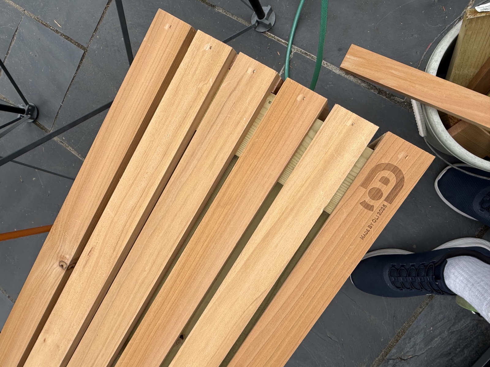 Long sides going on — overhang row at base by design
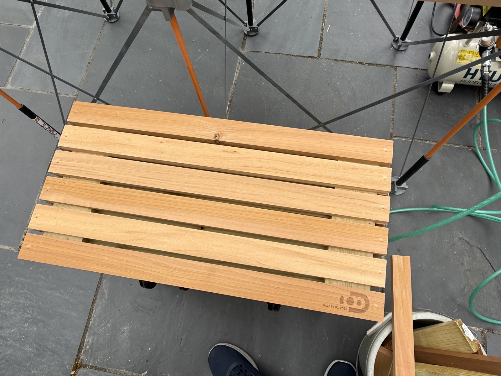 All four sides clad — top lip boards laid out for fitting, ready to nail down
Stage 5 of 5 · Finished Planter
Top lip nailed down — long boards first, short boards fitting in between. Casters mounted on the underside via pre-drilled pilot holes. The finished planter sits clean on all four wheels, ready for sanding, oiling, and the liner before planting. Total material cost: £173.
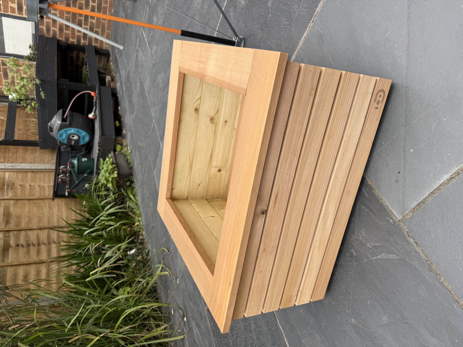 Finished — top lip on, cedar complete, casters fitted
626 × 626 × 338 mm · Western Red Cedar · £173 in materials
Finished — top lip on, cedar complete, casters fitted
626 × 626 × 338 mm · Western Red Cedar · £173 in materials
Two timber profiles, 60 pieces to cut. Corner posts are built from the same 74 × 22 mm stock — no separate sourcing needed. Stainless steel nails and waterproof wood glue throughout.
Budget
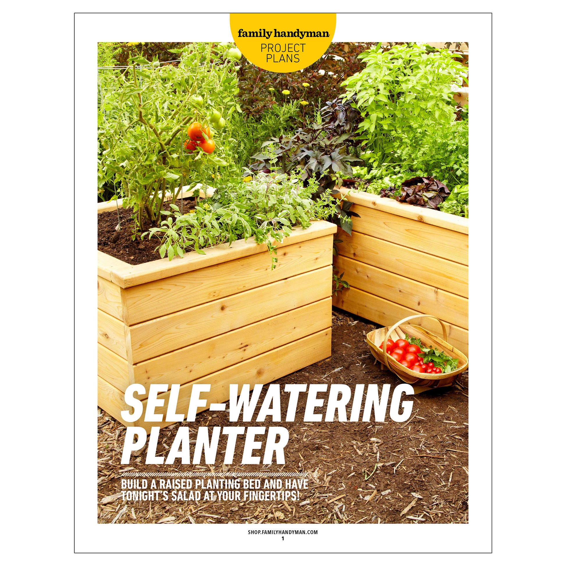
Context — equivalent planters available to buy ready-made
Why build your own?
| Product | Retailer | Size | Material | Price |
|---|---|---|---|---|
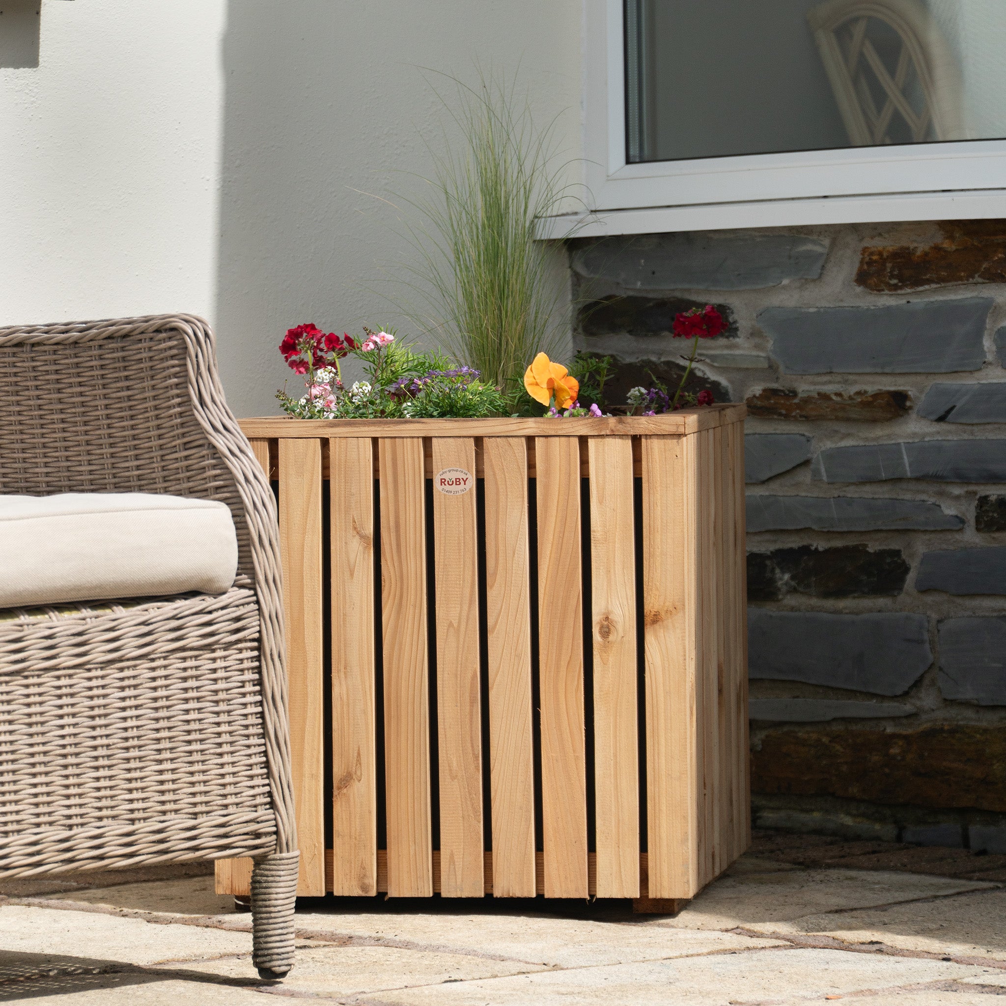
| Premium Cedar Vertical Slatted Panel Planter | Ruby | 500 × 500 mm | Cedar | £168 |
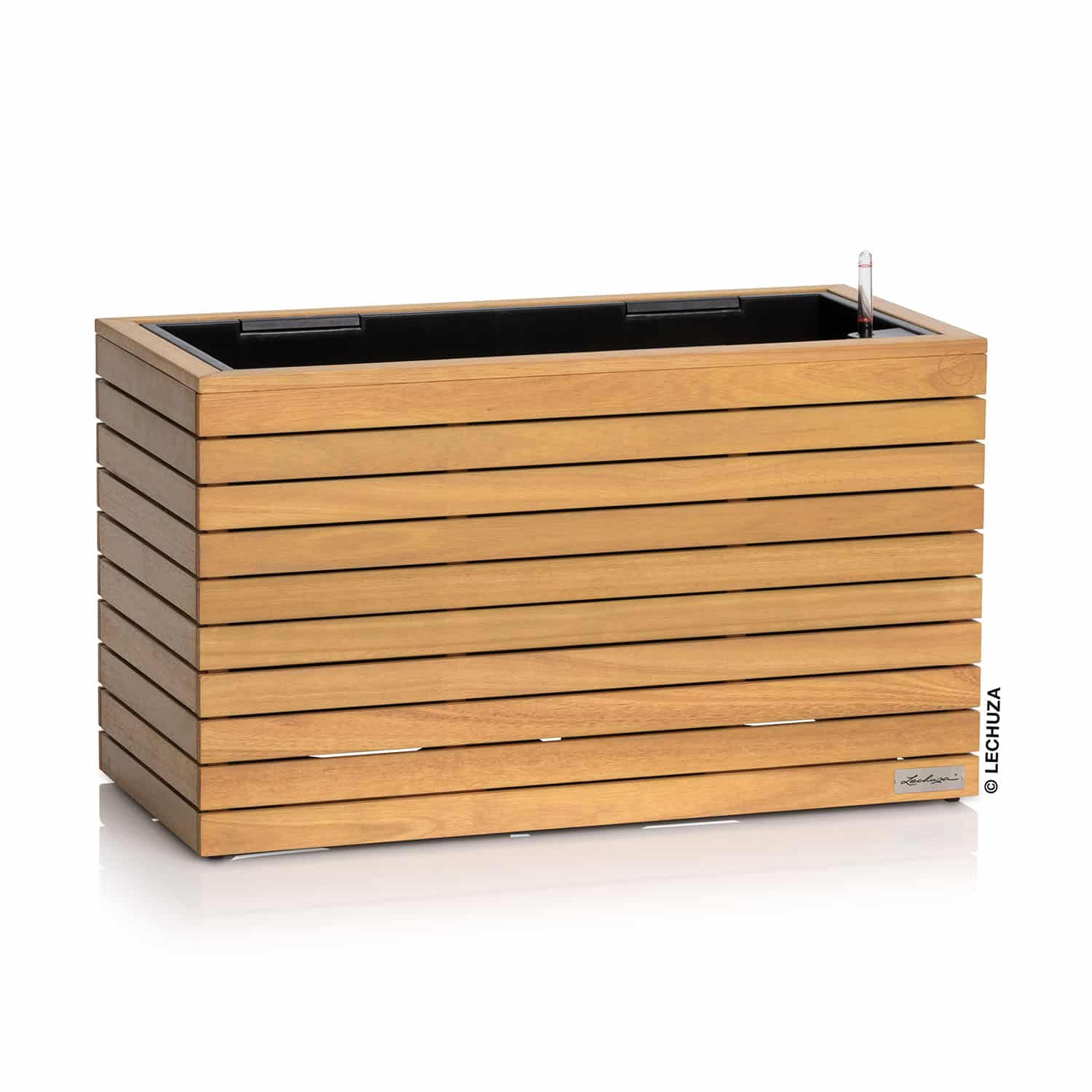
| PALO Self-Watering Wide Wood Trough Planter | PALO | 790 × 370 × 770 mm | Eucalyptus | £482 |
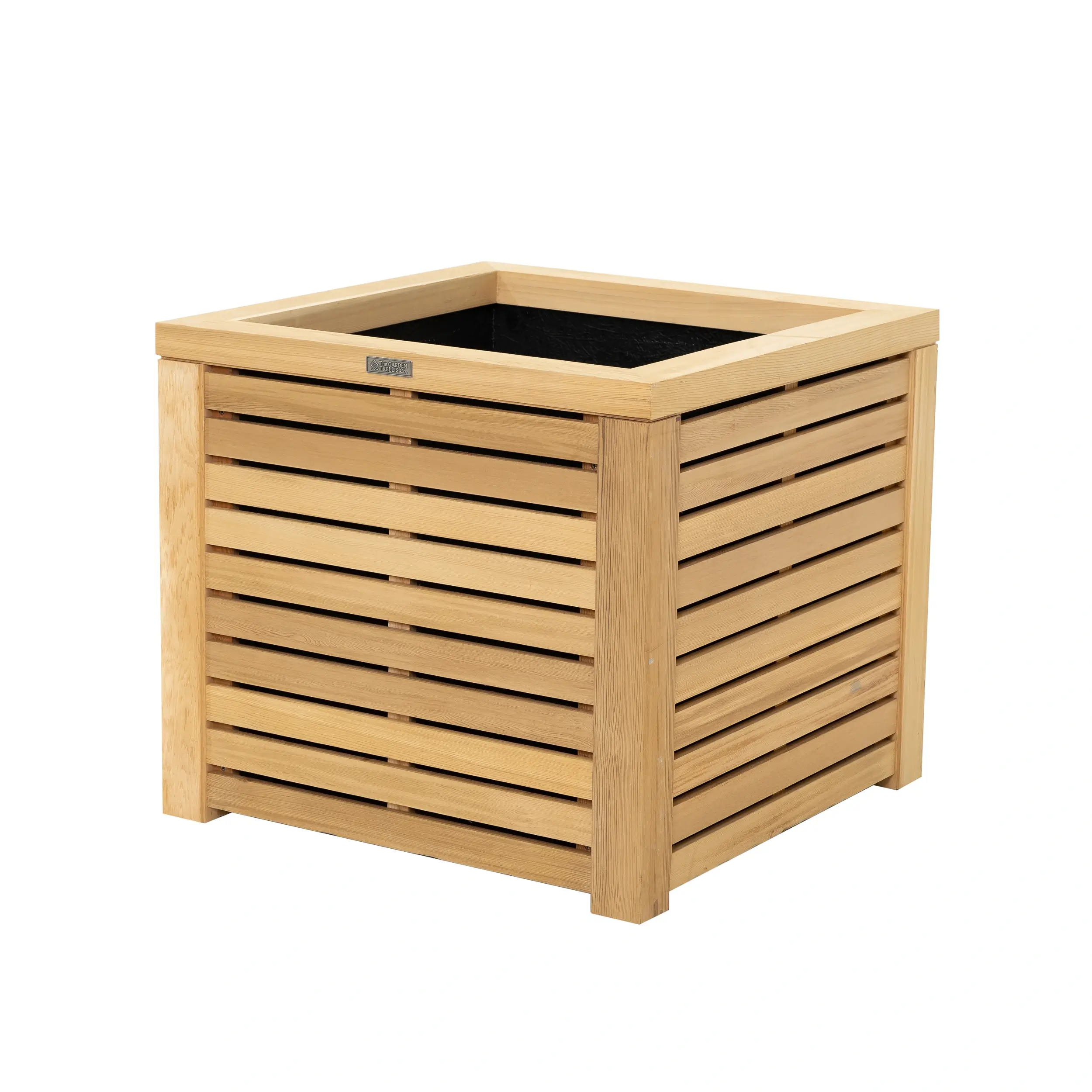
| RHS Prestige Slatted Square Planter | The Garden Trellis Co. | 500 × 500 × 525 mm | Western Red Cedar | £770 |
| This build | Self-build | 626 × 626 × 338 mm | Treated pine + Western Red Cedar | £173 |
Prices as of May 2026 — subject to change
All items, sourced from three suppliers
| Item | Source | Qty | Unit price | Total paid | True cost |
|---|---|---|---|---|---|
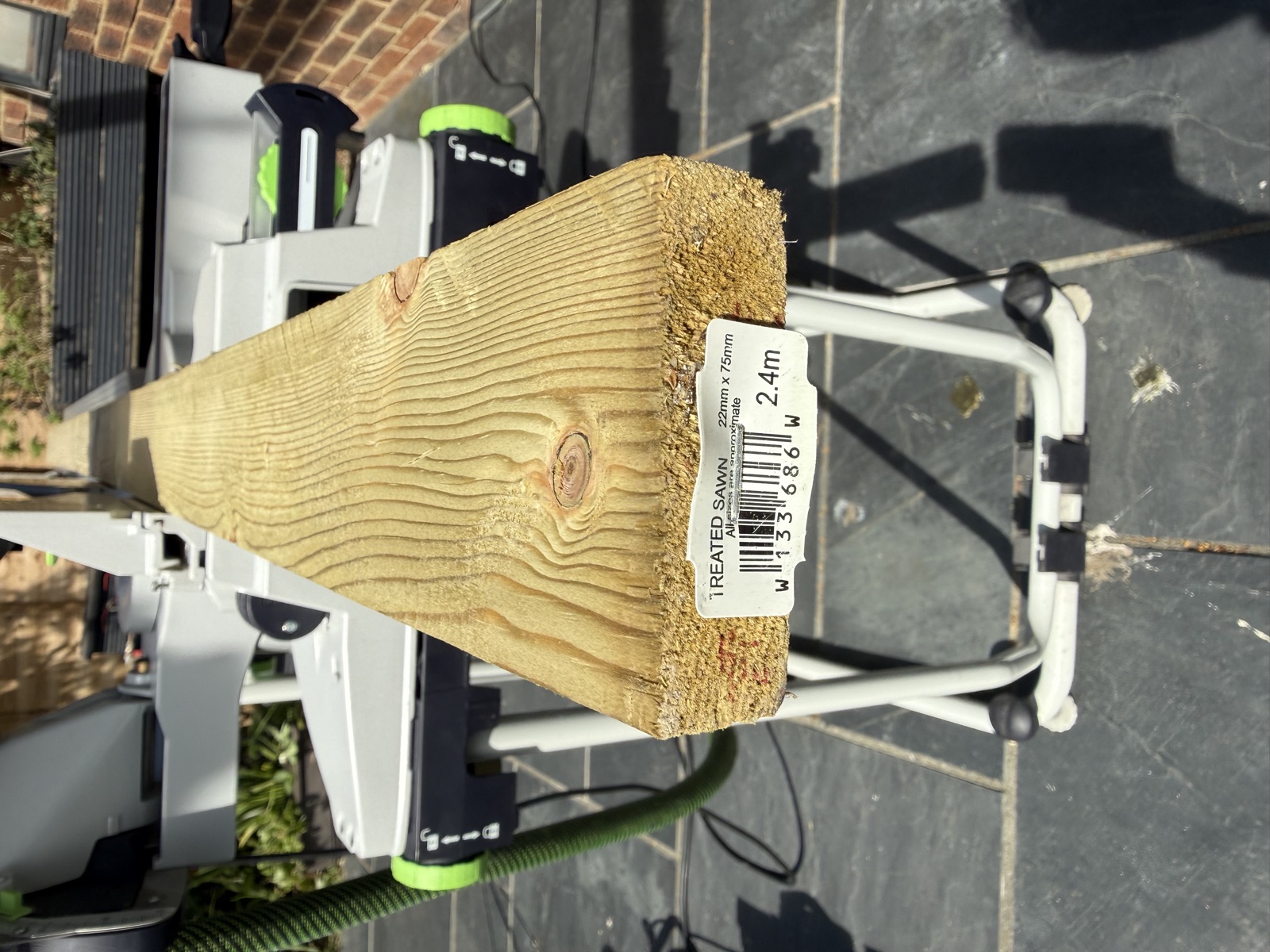
| Treated sawn timber — 22 × 75 × 2400 mm | Wickes | 6 | £7.60 | £45.60 | £45.60 |
| Red cedar battens — 44 × 18 mm × 1830 mm | Contemporary Fencing | 1 pack | £72.00 | £72.00 | £72.00 |
| GBL heavy duty swivel caster wheels 50 mm — pack of 4 with brakes | Amazon | 1 pack | £11.63 | £11.63 | £11.63 |
| Tacwise 16G stainless finish nails — 32 mm, pack of 1000 | Amazon | 1 | £15.45 | £15.45 | £2.29 (148 nails) |
| Tacwise 16G stainless finish nails — 50 mm, pack of 1000 | Amazon | 1 | £17.93 | £17.93 | £1.15 (64 nails) |
| Titebond III Ultimate Wood Glue — 8 oz (236 ml) | Amazon | 1 | £10.26 | £10.26 | £4.35 (~100 ml) |
| Total | £172.87 | £137.01 | |||
Profile A — board cutting plan (6 boards × 2400 mm)
Wickes treated sawn timber — 22 × 75 × 2400 mm @ £7.60
| Board | Cuts | Used | Waste |
|---|---|---|---|
| 1 | 8 × 300 mm — corner post arms | 2400 mm | 0 mm |
| 2 | 4 × 516 mm — long wall slats | 2064 mm | 336 mm |
| 3 | 4 × 516 mm — long wall slats | 2064 mm | 336 mm |
| 4 | 5 × 472 mm — short wall slats | 2360 mm | 40 mm |
| 5 | 5 × 472 mm — short wall slats | 2360 mm | 40 mm |
| 6 | 4 × 472 mm — floor slats | 1888 mm | 512 mm |
| Total | 13 136 mm | 1 264 mm | |
Product notes
| Item | Notes |
|---|---|
| Caster wheels | GBL 50 mm heavy duty swivel castors rated to 200 kg total (50 kg per wheel) — more than adequate for a planted box. The pack of 4 includes brakes and fixing screws. The 50 mm wheel diameter sets the minimum floor height in Step 05. |
| Nails — 32 mm | Tacwise 16G Type 16/32 stainless steel finish nails (pack of 1000). Used for cladding, top lip, and floor slats. The guide references 30 mm; 32 mm is the nearest available size and works identically for this application. |
| Nails — 50 mm | Tacwise 16G Type 16/50 stainless steel finish nails (pack of 1000). Used for wall slats nailed into the deep face of the corner posts. You will have plenty left over from both boxes. |
| Wood glue | Titebond III Ultimate is a Type III waterproof (D4-rated) glue — the correct choice for outdoor use where joints will be wet. The 8 oz (236 ml) bottle is sufficient for this build. Do not substitute with standard PVA. |
Context
Ready-made alternatives — what you would pay to buy instead
This build
Custom Cedar Planter with Swivel Castors
626 × 626 × 338 mm · Western Red Cedar cladding on treated pine frame · 4 swivel castors · fully customised
£173
material cost
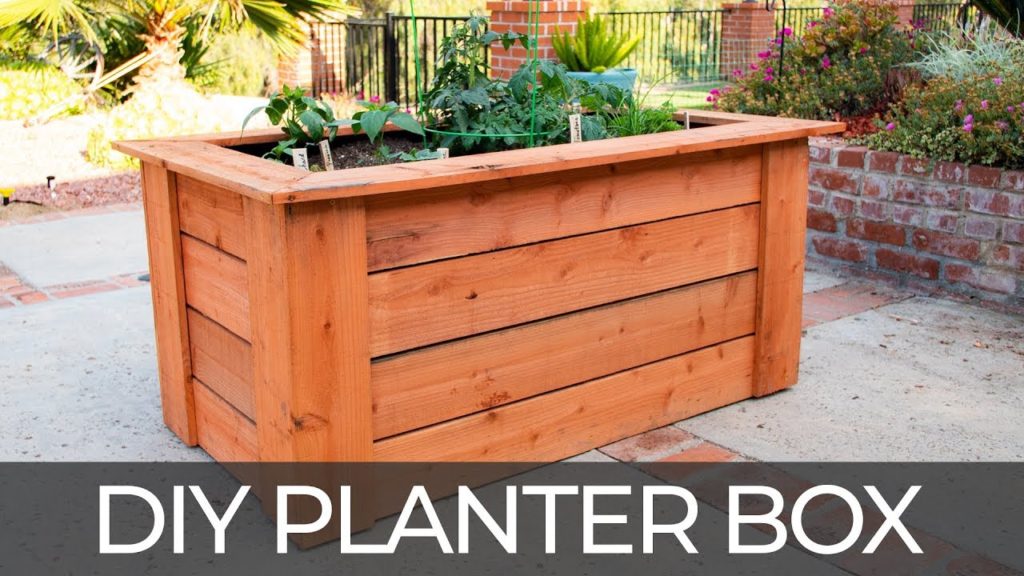
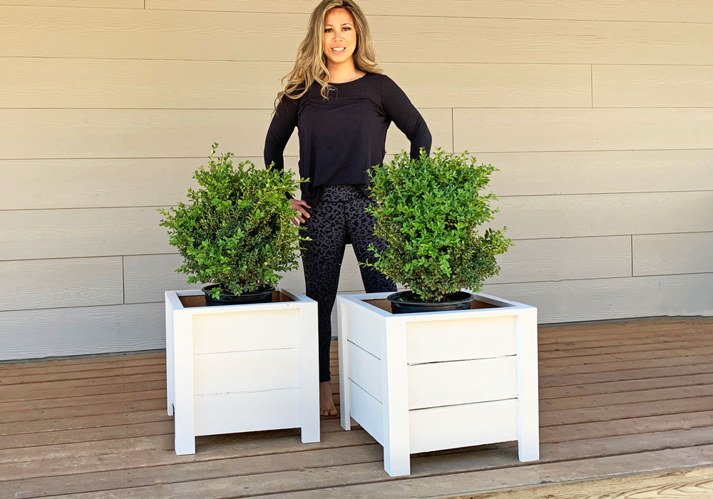
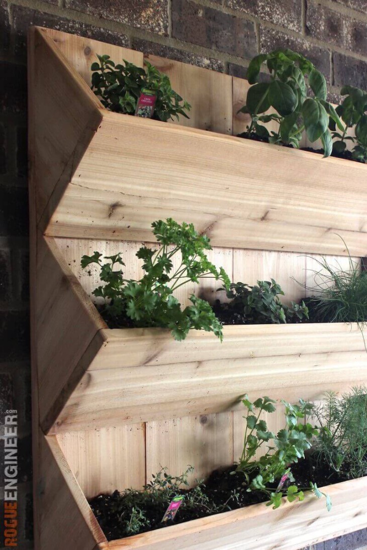
Similar DIY builds found online
The horizontal slat pattern, L-post corner construction, and hidden-caster rolling base together make this design distinctive among DIY cedar planter plans available online.